AI Thinker ESP32-A1S Audio Kit v 2.2 board.
No-name SSD1322 display, with 0-Ohm resistors set to 4-wire SPI mode.
KY040 rotary encoder.
squeezelite-esp32 firmware version ESP32-A1S.552.master-cmake
Much experimenting required to get a working permutation of GPIO selections. With assistance from the forums, I have eventually found that the following configuration:
display_config:
SPI:width=256,height=64,cs=0,reset=19,speed=8000000,driver=SSD1322,HFlip,VFlip,rotate
spi_config:
data=22,clk=13,dc=5,host=1
rotary_config:
A=23,B=18,SW=15
DIP switch positions, reading left to right: Off/Off/Off/On/On.
Wired as follows:
| LCD | ESP32 Audio Kit | squeezelite-esp32 parameter |
| 1 – Ground | GND | |
| 2 – 3V3 | 3V3 | |
| 4 – SCLK | IO13 (labelled MTCK) | spi_config: clk=13 |
| 5 – SDIN | IO22 | spi_config: data=22 |
| 14 – DC | IO5 | spi_config: dc=5 |
| 15 – Reset | IO19* | display_config: reset=19 |
| 16 – CS | IO0 | display_config: cs=0 |
| Rot Enc | ESP32 Audio Kit | squeezelite-esp32 parameter |
| CLK | IO18 | rotary_config: B=18 |
| DT | IO23 | rotary_config: A=23 |
| SW | IO15 (labelled MTDO) | rotary_config: SW=15 |
| + | 3V3 | |
| GND | GND |
gives a working display + rotary encoder.
When relocating Reset, I noticed that the display does not seem to require it.
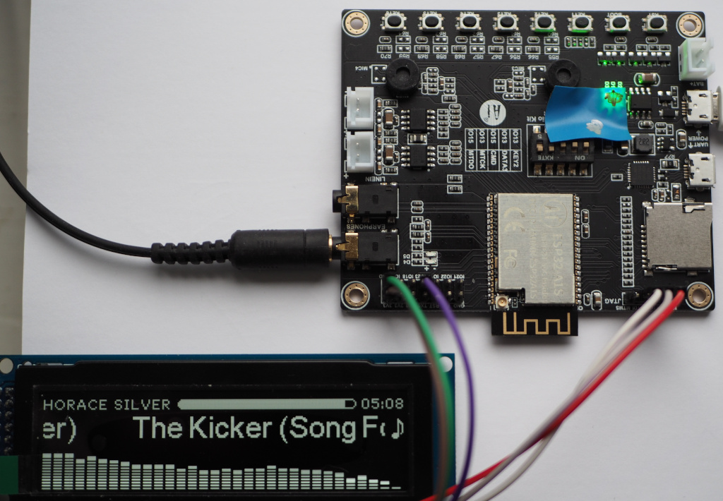
Why is there some electrical tape on it? Because the LEDs on the board, particularly D1, are obnoxiously bright.
Amplification is provided by 2x NS1450, “a Low EMI, Filterless, 3W Mono Class D Audio Amplifier”, with the caveat being that it’s only filterless if the wire to the speakers is less than 100mm.
Todo: build an enclosure, acquire some suitable speakers, have a look at what types of batteries this thing can manage.
Bill of materials so far:
ESP32-A1S Audio Kit – £10
3.12″ SSD1322 OLED display – £16
3x JST XH 2-pin connectors – £1.8
12x DuPont jumpers – £2
1x HW040 rotary encoder – £0.8
Took quite a while to find a permutation of GPIOs that let the amp, rotary encoder and the display work simultaneously.
set_GPIO 21=amp,39=jack:0
It seems like there is some interaction between GPIOs that isn’t what you’d expect from the actual GPIO numbers.
Thoughts on this so far
First, the negatives:
Audio quality isn’t great. Higher frequencies are a bit mushy. Fine for building a little portable streaming speaker, though.
Documentation for this board is sparse. The manufacturer’s pages are all now 404s.
Green LED D1 is needlessly bright.
The GPIO assignments are bit mysterious [although to be fair, this is the first ESP32 project I’ve done]. Changing one thing causes others to mysteriously stop working. The 5 DIP switches on the board are confusing labelled – they are all labelled IO13 or IO15, but MTDI is IO12.
The firmware is not “done” yet. I have had the occasional core dump/reboot, but I expect this to improve with time.
The positives:
It’s very cheap. £10 delivered to the UK.
It’s all in one – buttons, DAC, amp and charge controller – but with the caveat that the GPIOs are what they are, and that’s that.
What are the alternatives?
Raspberry Pi Zero W [£10] + HiFiBerry Pi Zero MiniAMP [£15.5] + an SD card. Identical power output specs, probably better audio quality. Would need to do something for battery management. More than twice the price. piCorePlayer would be the obvious OS to run on this.
ESP32 WROVER board + DAC + amp. Bit more work selecting the components to use but no fussing with GPIO confusion.
Olimex ESP32-ADF – very similar specs to the ESP32 Audio Kit. Can’t confirm that it works with squeezelite-esp32. Note that Espressif’s software framework is called “ESP-ADF” and this piece of hardware from Olimex is called “ESP32-ADF”, so have fun googling that!
What else could be done with an ESP32 Audio Kit?
Wifi intercom – a pair of these could work back-to-back with some kind of SIP stack running on each. Press a button, a call is set up to the other unit and audio starts flowing between them immediately. More than two and you’d need an external server to do the audio mixing [eg, Freeswitch]. Call setup times would have to be pretty rapid for this to work.
Power consumption
Figures are per minute. Tested with a cheap UT-25 type USB tester.
- Playing through the speakers, volume level 24: 18mWh
- Through the headphone jack at volume level 30: 18mWh
- Idle, or “off”: 8mWh
- Display off in “off” mode: same!
- Changed clock mode to hh:mm [ie, no seconds]: 6mWh
Two surprises here: the OLED being off or on seemed to make no difference to the power consumption, and neither did running through the speakers vs. headphones. Waking up regularly to process display updates seems to be relatively expensive.